
Teaching Aids
In my time at The Chalfonts Community College, I have produced many teaching aids for multiple different departments. Please have a look at the assorted selection below.
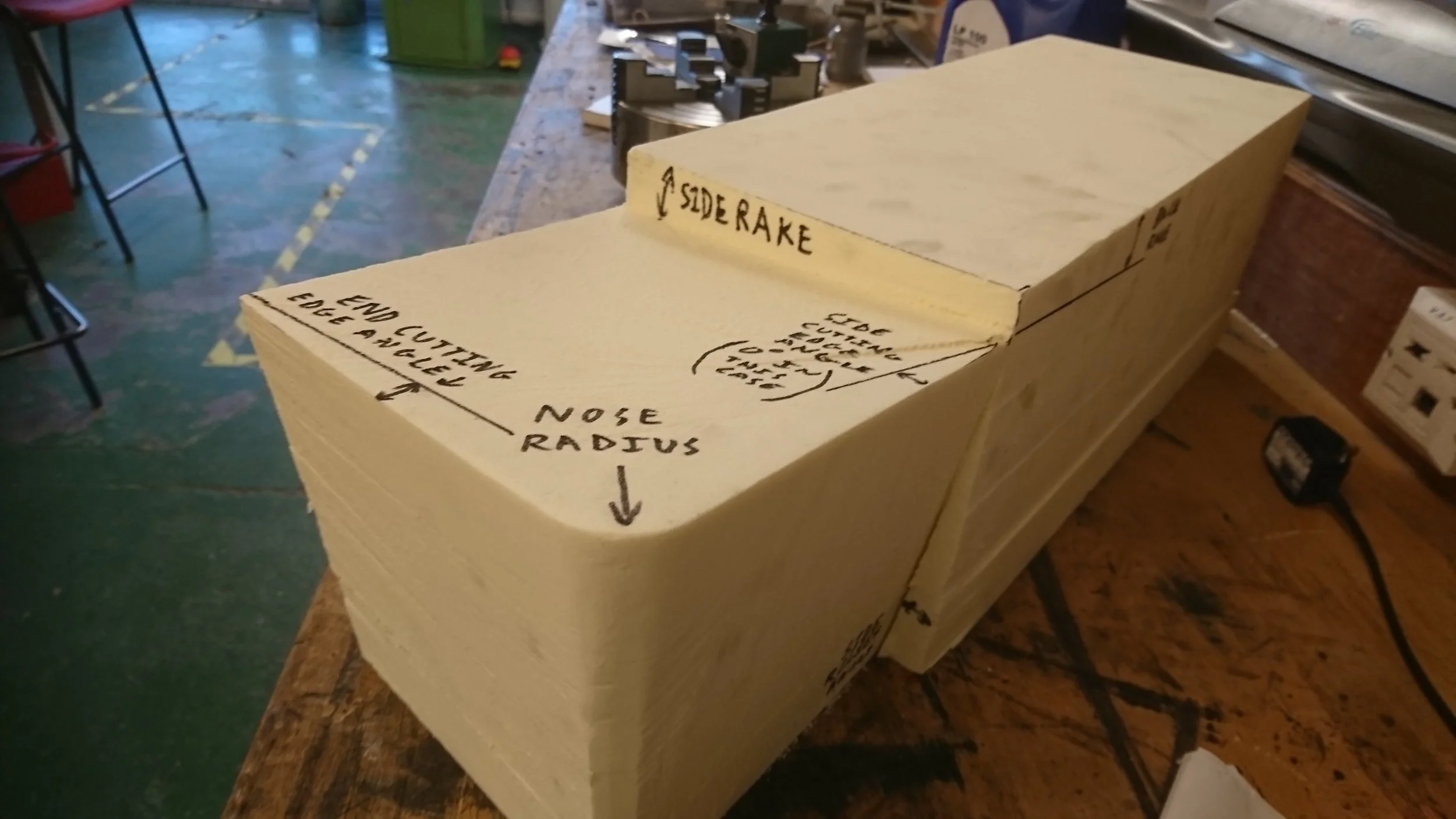
To aid in teaching about lathe tool geometry, I made this giant lathe tool from modelling foam. Each feature was then labelled.

Once a demonstration was given, explaining the reasons for each relief angle, the students were given their own piece of foam, albeit rather smaller than this one and tasked with shaping it using files and sandpaper to the correct geometry.
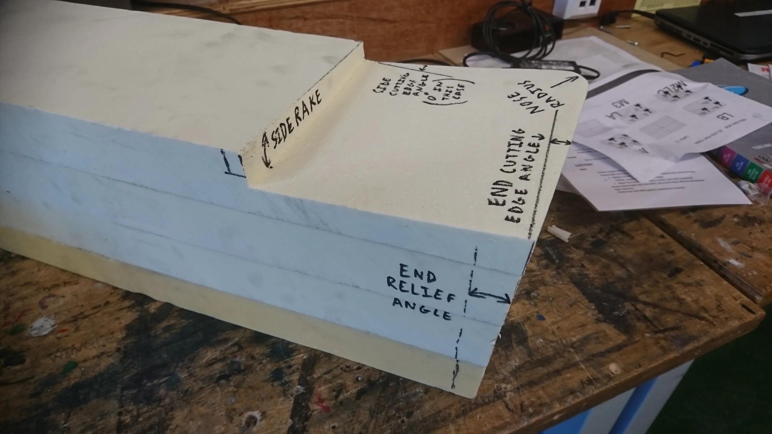
This really helped to visualise and fix this terminology, without becoming tedious rote learning.

Given only one week's notice, I was asked by the Geography department if I could make some pieces for their upcoming 'Sustainable Cities' project. Geography: "Would it be possible to have a few laser cut acrylic solar panels and some 3D printed wind turbines?" Me: "Sure!" Geography (walking away): "And how about a hydroelectric dam?" Me: "Now you're talking!"

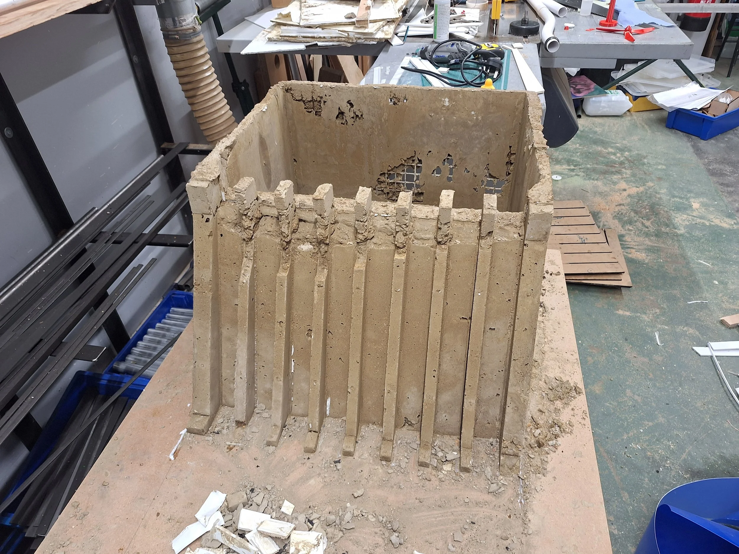
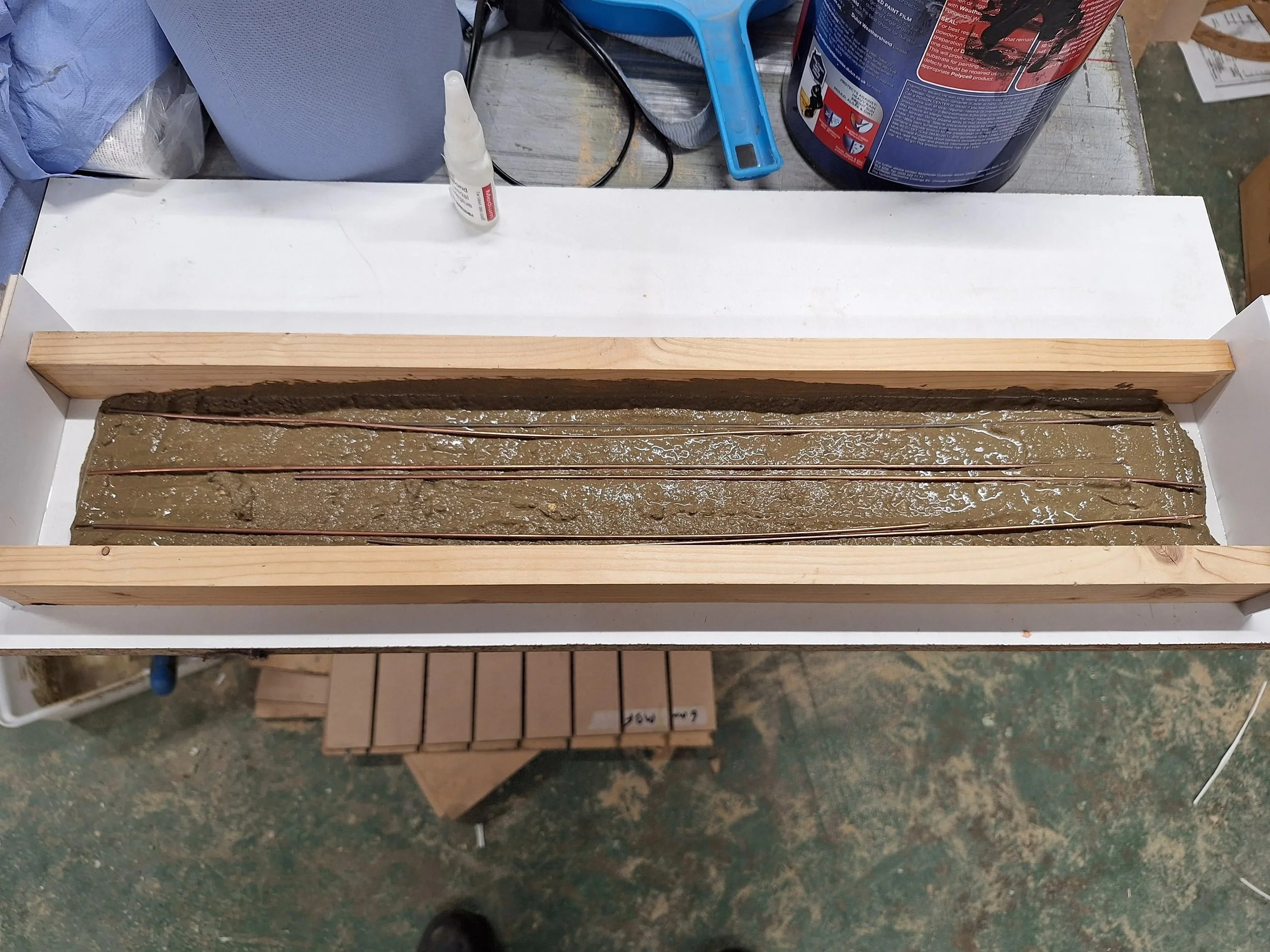
I drew up this design, with a view to casting the dam in reinforced concrete, which though it may seem excessive to the casual observer, I decided was probably the easiest way to produce a water-tight tank and the other features required.

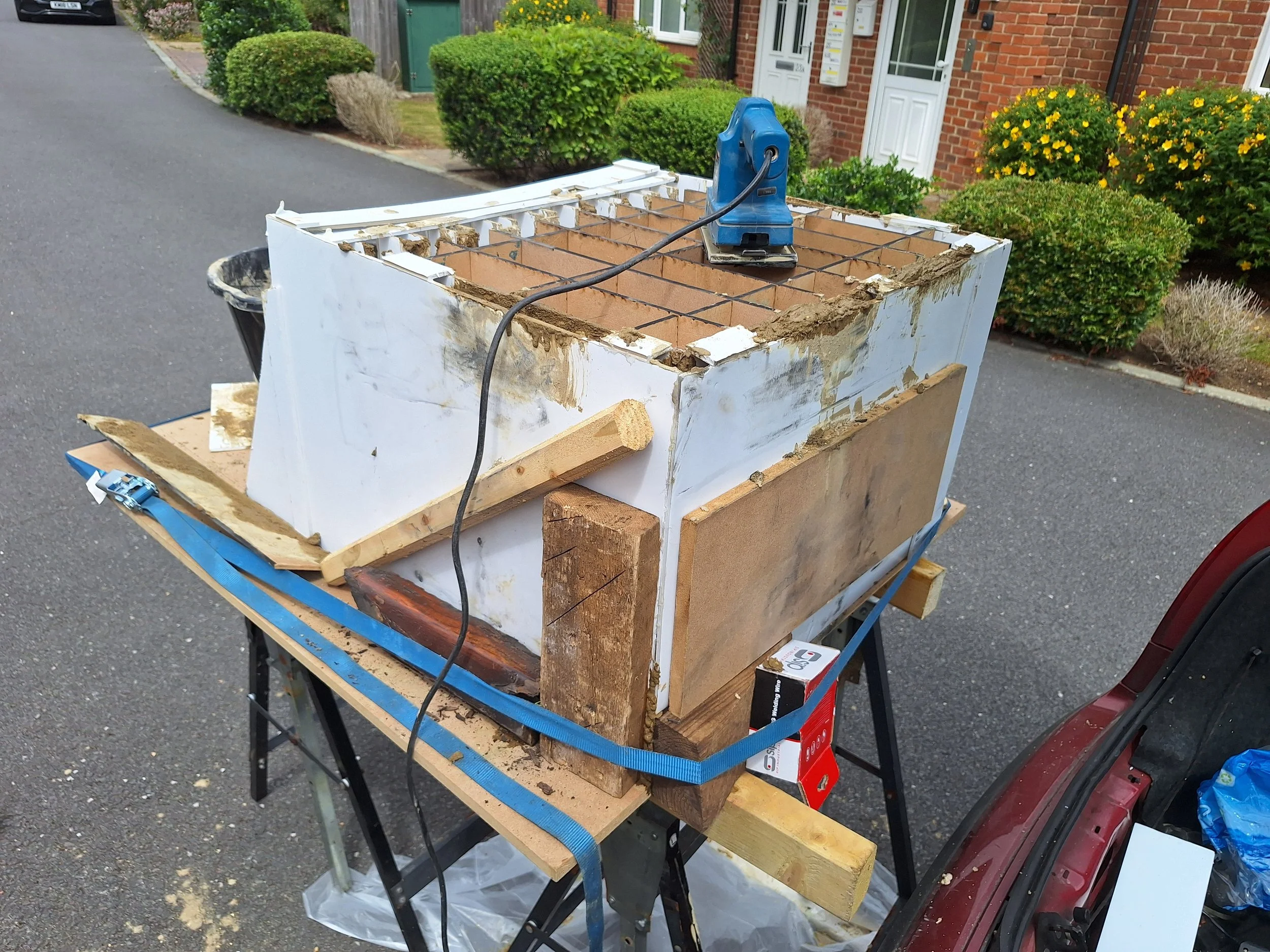
I used a combination of hand cut and laser cut foam-board components, assembled with hot glue, to form a mould. The reservoir tank needed to be reinforced, so I used some weld mesh that was left over from a prior project. This was all mounted on a thick MDF base.

Some TIG rods provided reinforcement for the spillways and accompanying buttresses.

Concreting was done alongside helping a friend work on his car, so some trestles behind my car facilitated loading in and out.
An oscillating electric sander, minus its abrasive paper, was used to vibrate the concrete into the walls of the form, attempting to eliminate voids.
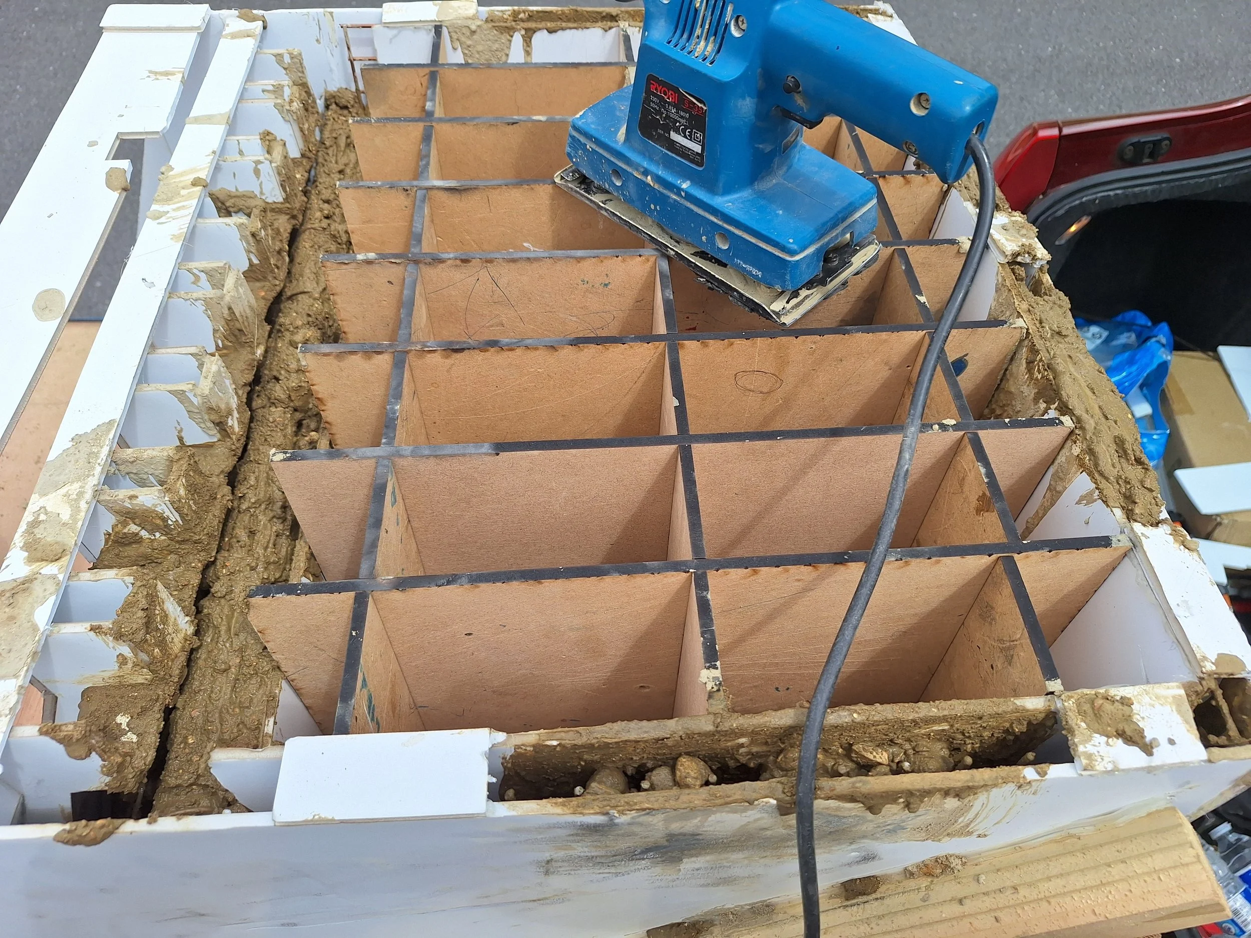
This MDF grid structure slotted together inside the tank to support the foam board mould.

Concrete was mixed up using a mix of approximately 4:1 aggregate to cement with water added until the required slump was achieved. The aggregate was a mix of ballast and sharp sand, with the larger ballast gravel having to be picked out by hand, in order to fit around the weld mesh reinforcement.

Wall thicknesses were only 30mm, held at thickness by these spacers at the top of each wall. In hindsight, extra bracing was required to the exterior walls as bowing occurred as the concrete level rose, and had to be contained with ratchet straps and wood blocks. I will blame it on the rushed schedule that I realised this for the interior faces, but forgot the exterior ones!
The casting, as removed from the mould. Not perfect. With hindsight, a mix with just sharp sand would have worked better and a slightly looser mix. Unavoidable was the scorching summer weekend that I poured this on, which did not give me as much working time as I would have preferred!
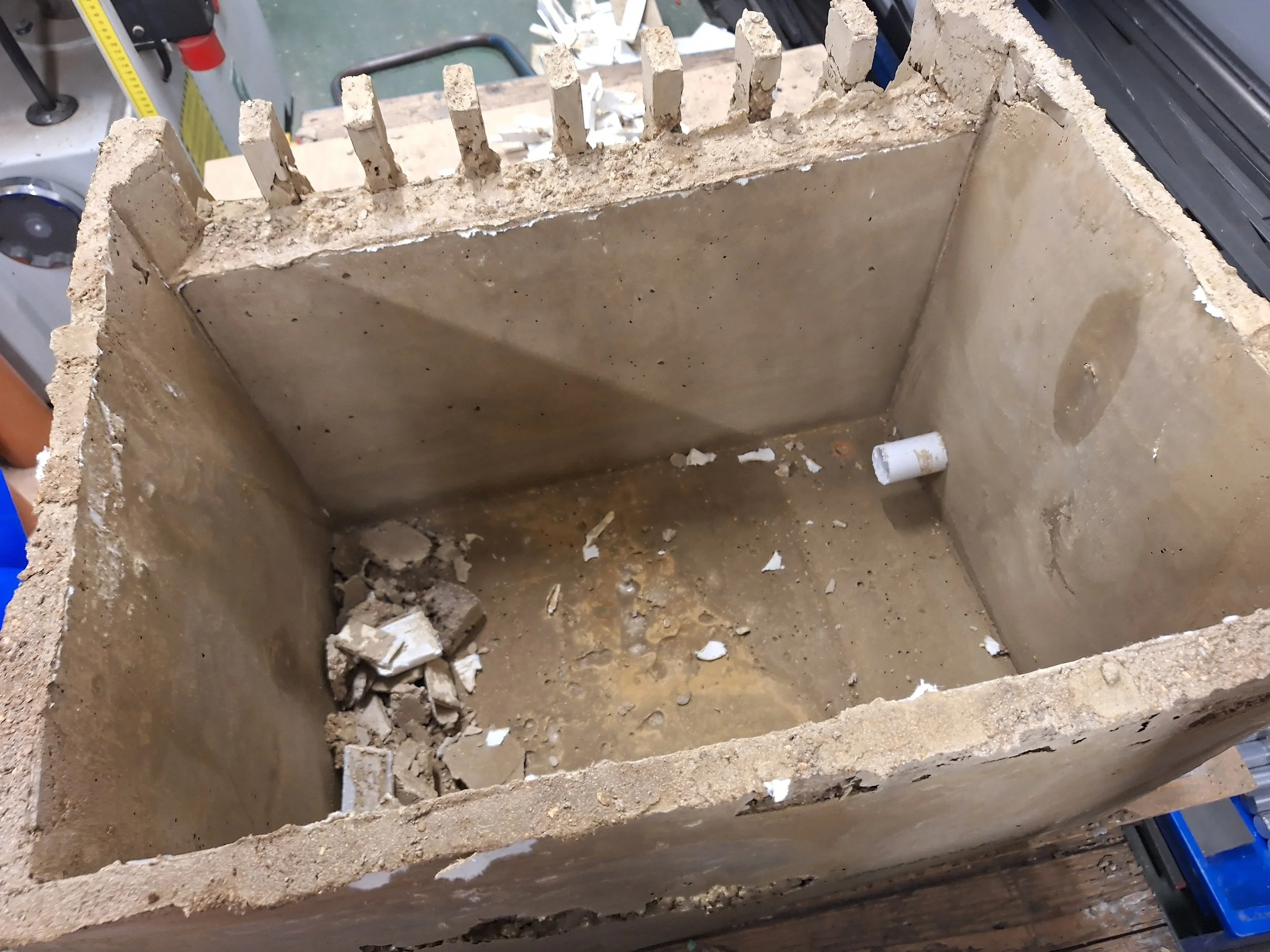
Here you can see the cast-in-situ PVC pipe that formed the outflow for the turbine.
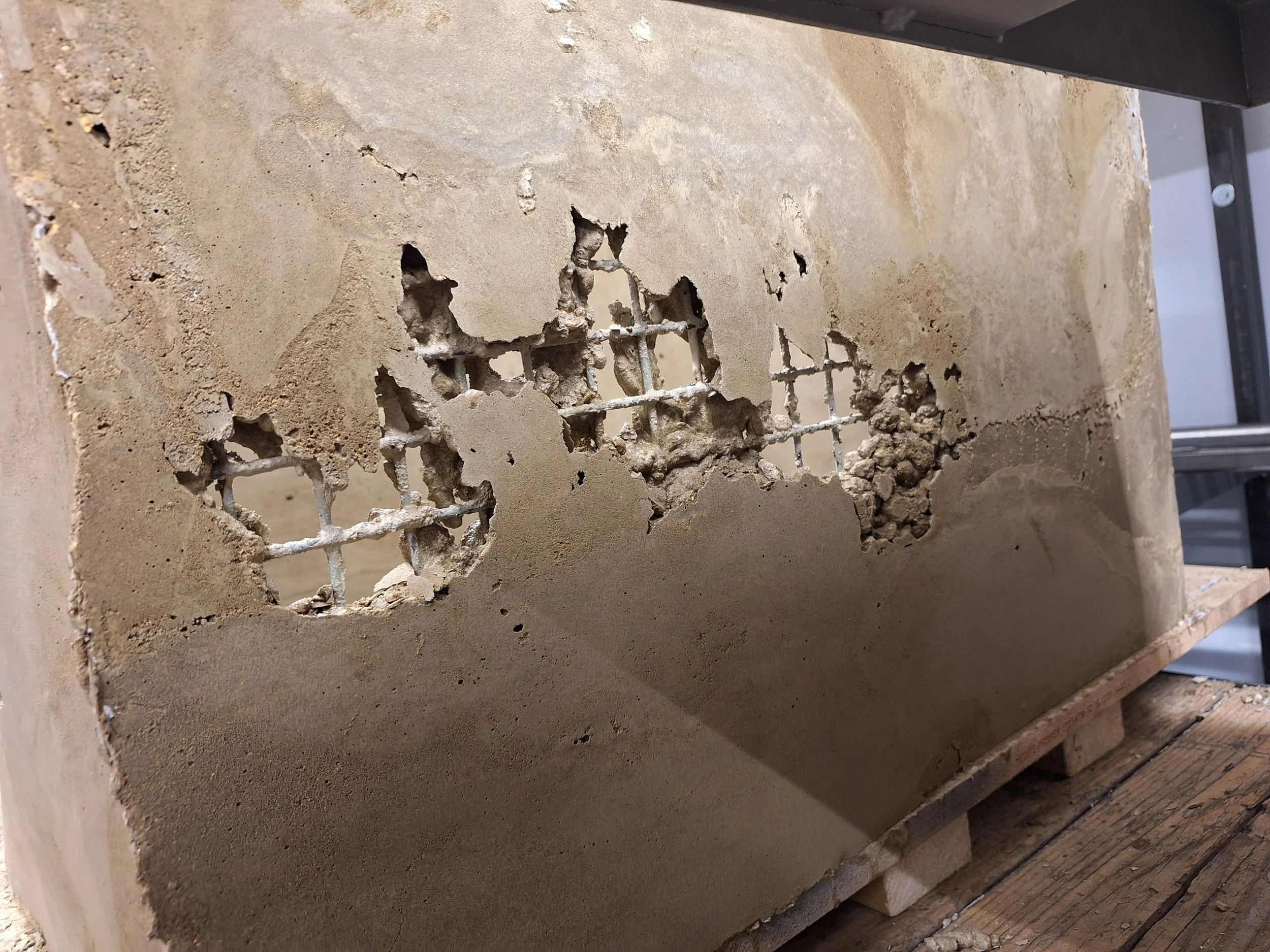
These voids were repaired by filling with a sharp sand and cement mix. Some formwork was reattached to the interior and exterior faces before filling from a small hole at the outside top of the void. Copious vibration from the sander resulted in a properly repaired structure.
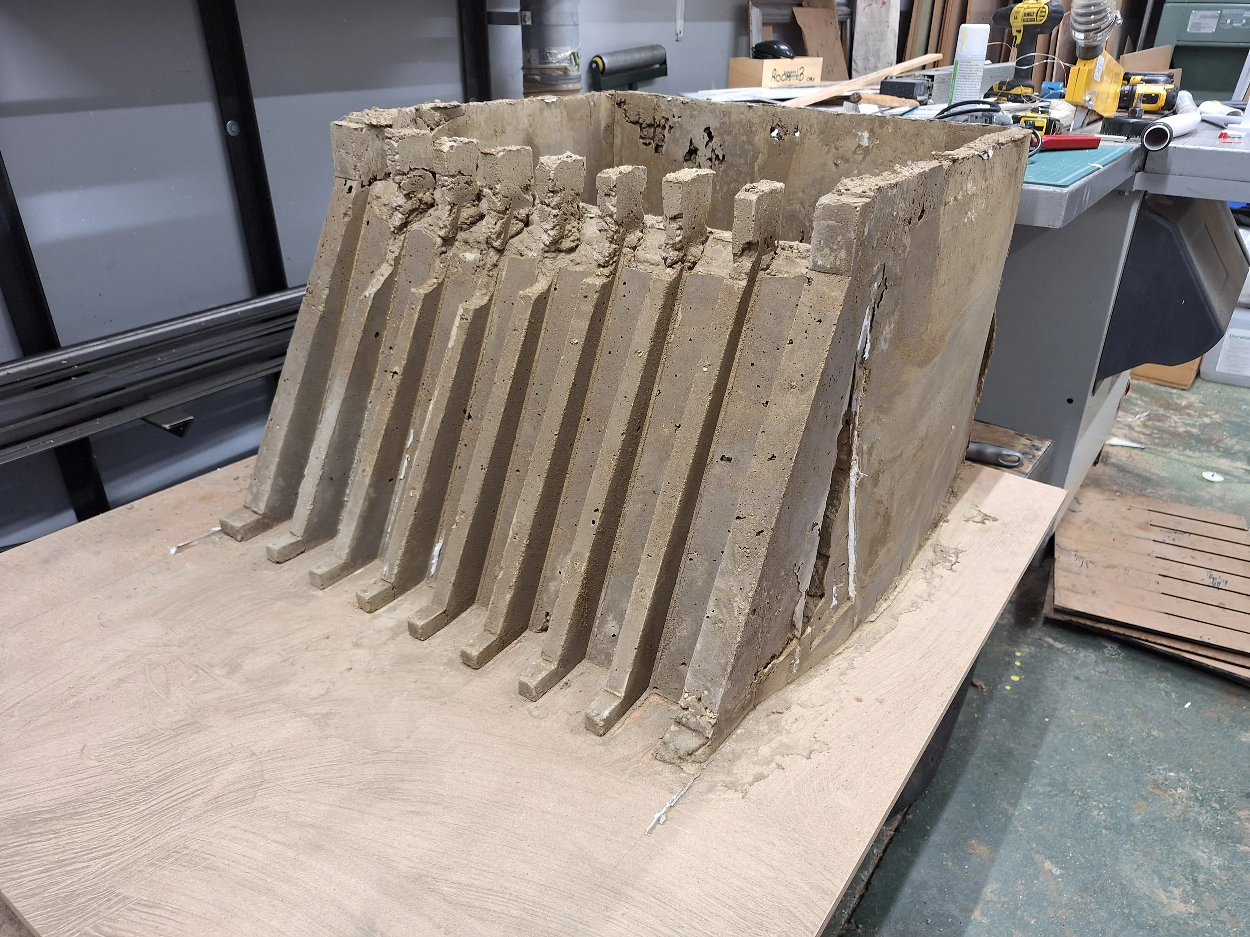
Some additional formwork was built up to repair the top of the buttresses that formed the bridge deck supports.

A couple of coats of masonry paint sealed the tank thoroughly, and a sharp sand and casting epoxy mix provided a "river bed" outfall. This was then plumbed into a catch bucket fitted with a sump pump to recirculate the water back to the reservoir tank.
This casting was to become the bridge deck.

This lathe backdrop was an early project of mine. A place for every tool and every tool in its place.
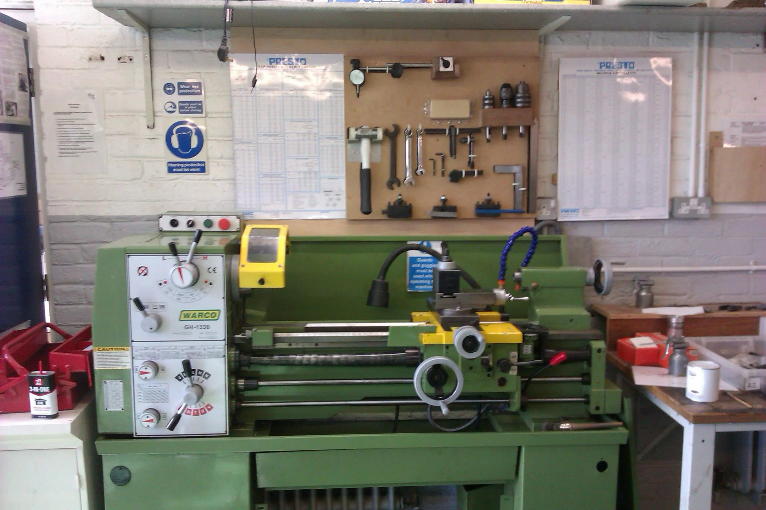
A combination of hooks, hardwood dovetails and blocks, line bent acrylic and folded aluminium ensured that all the components were safely held, then I drew around each tool and painted the enclosed area black, to ensure at a glance, that each tool could be accounted for. On either side of the board is a poster showing thread sizes and pitches and a metric/imperial conversion table. I repeated this for our second lathe, this ensured a consistent toolset for each lathe.
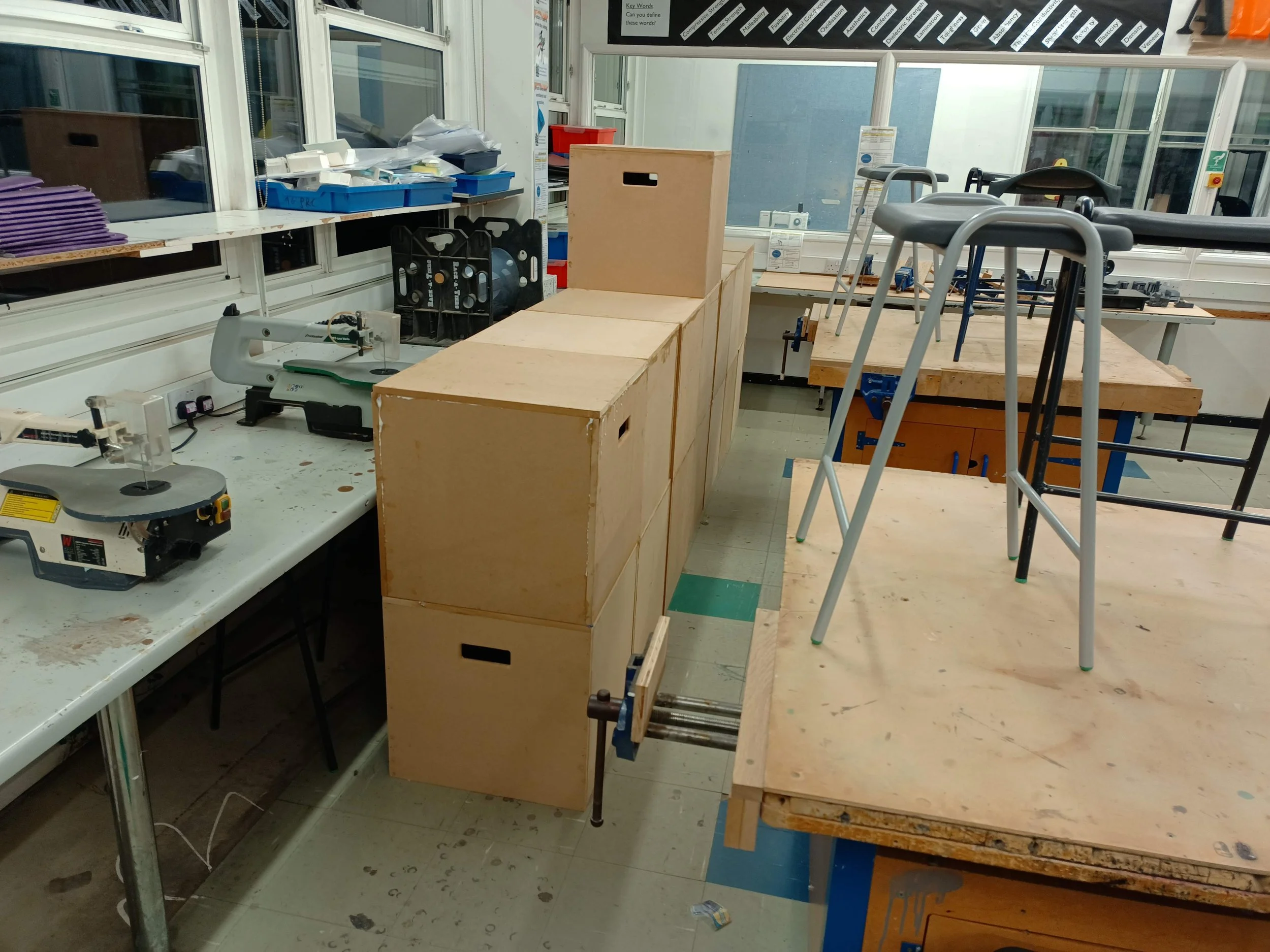
Some stage blocks built for (and with) Drama. I designed a kit of panels, including a router jig for the handle slots, to enable batch production of these boxes.
Drama students and teaching staff then spent a couple of after school sessions with me, firstly gluing and nailing each box together, before painting each block black. This saved the Drama department several hundred pounds versus buying pre-built blocks.

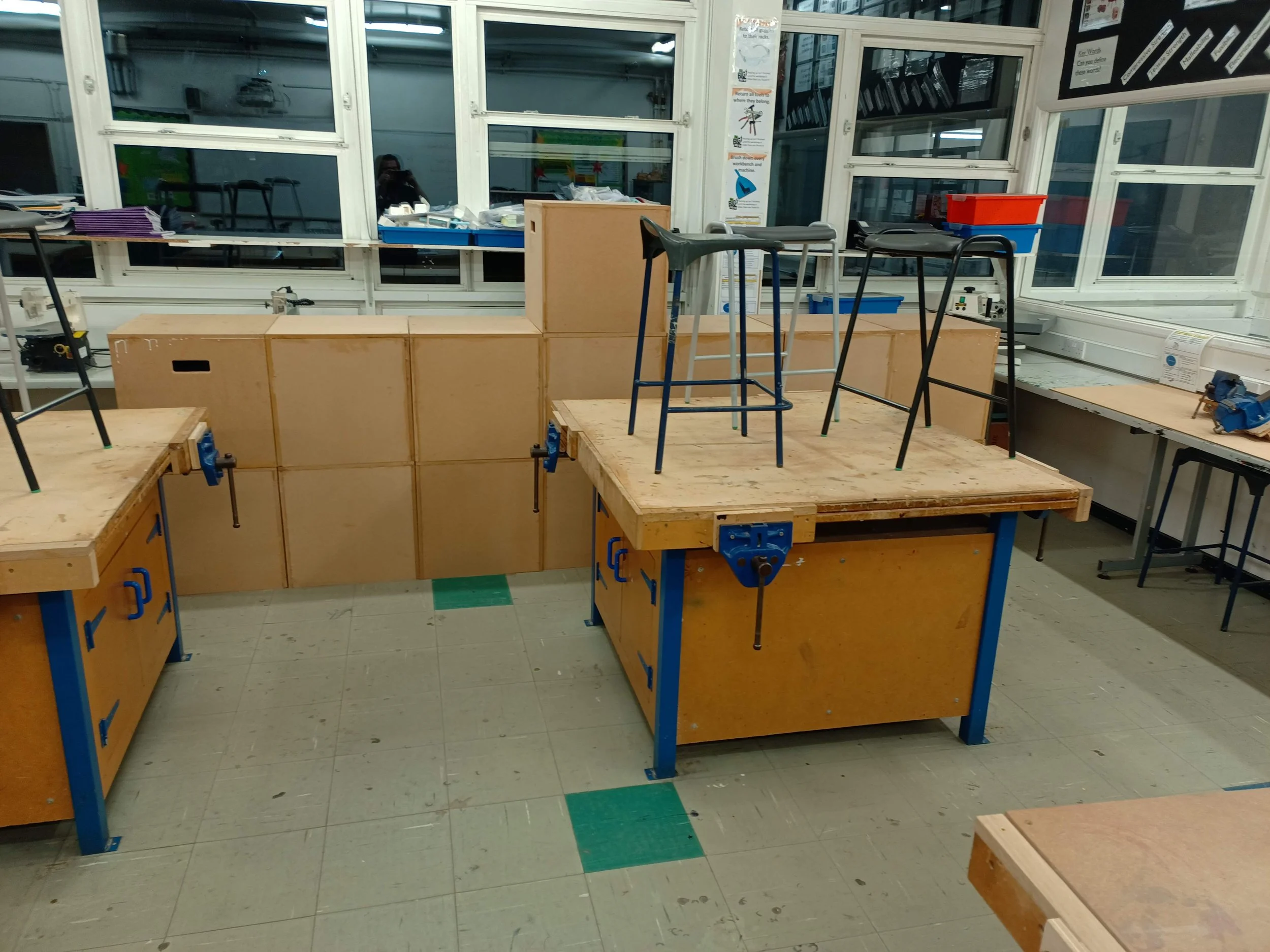
This tiered staging is a mock up for a 'bleachers' stage backdrop for 'Grease' the musical. We had the stage decks already and legs in two heights. I then determined the necessary lengths and quantity of additional legs required to achieve the desired stage layout.

I then ordered pre-cut aluminium scaffold tube and plastic plugs in the necessary numbers.
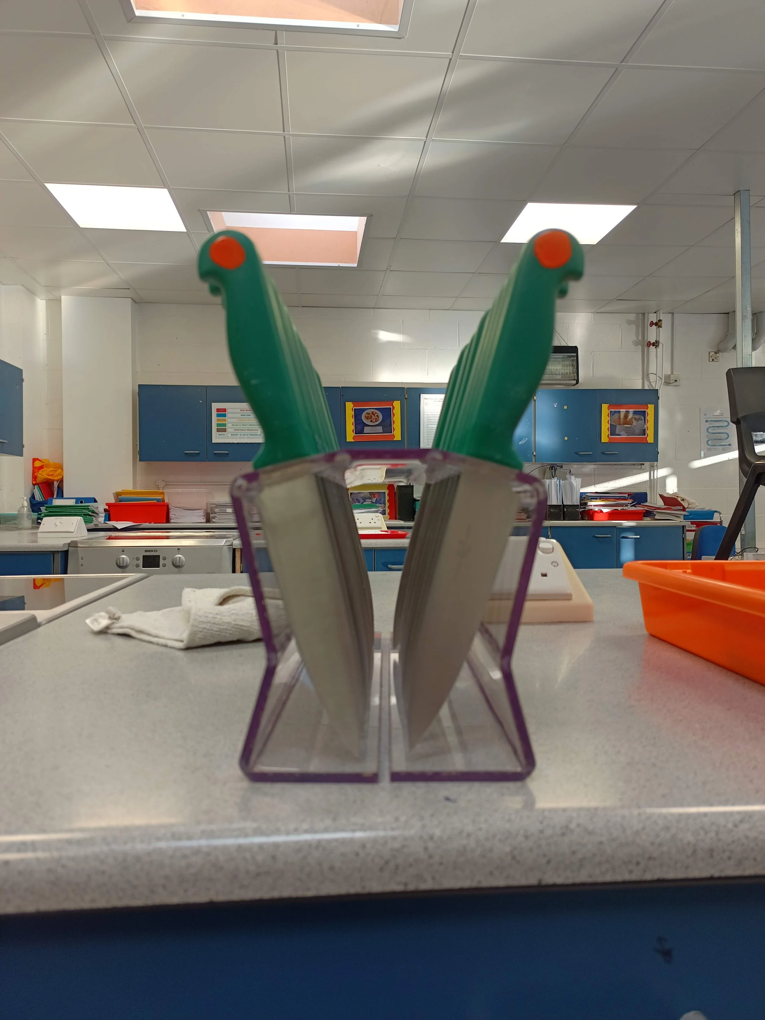
When Food Technology require knife blocks to store their chef knives, I realised upon a little research that there wasn't anywhere that sold a holder for 26 knives, each the same size!
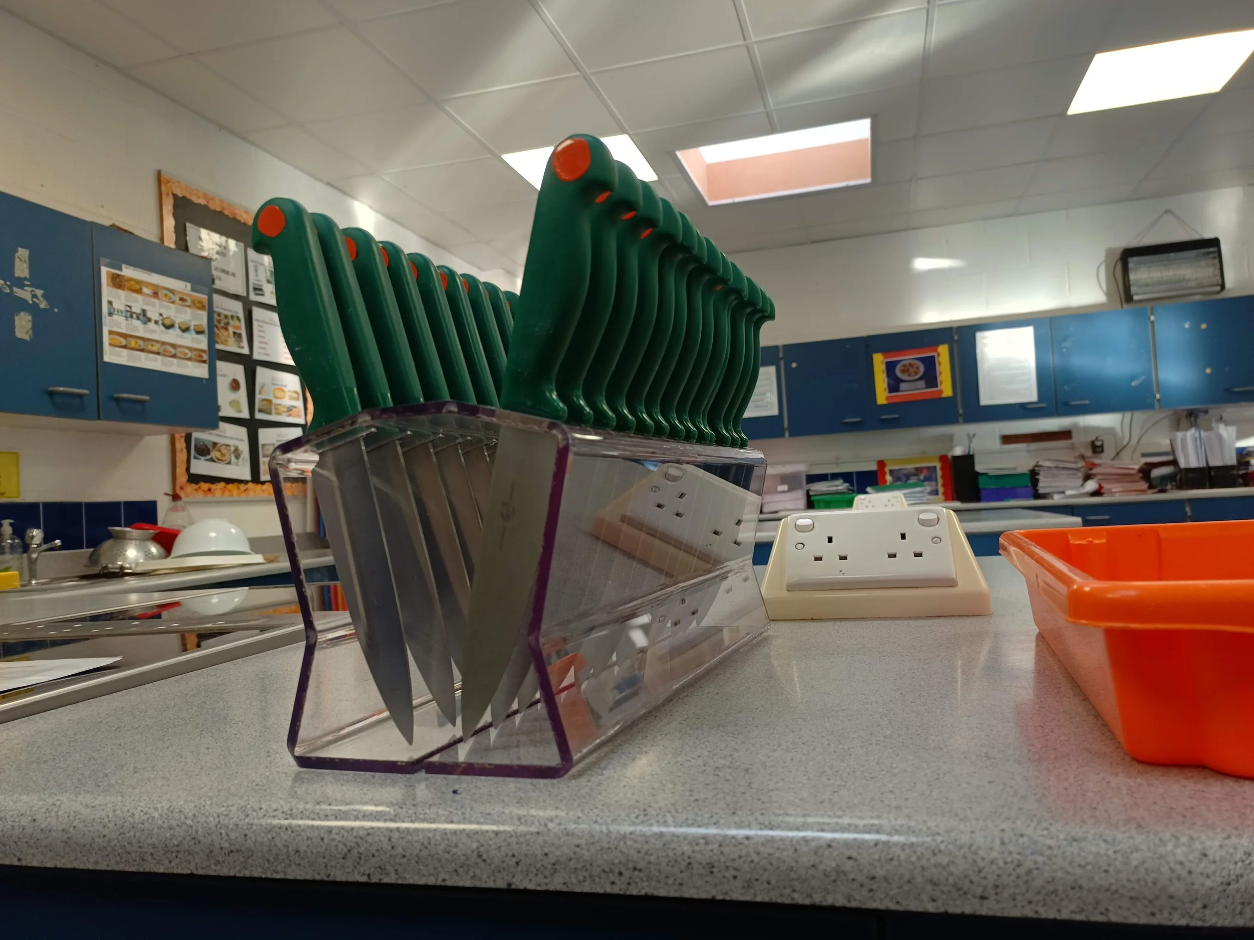
I designed this knife block from PETG for its food safe and easy clean features. The knife holes were laser cut, with the bend lines being engraved, then bent using a hot wire strip heater. The seam was at the bottom to enable any water on the knives to run out.

Oiled and waxed oak end-caps were later added to ensure that the blades could not be touched in transit. These were attached with wood screws to enable them to be removed for cleaning, but still requiring tools to do so.

A similar design yielded two smaller versions for these paring knives. These were likewise fitted with hardwood end-caps.

Notice how the handles are canted to the outside, but the blades do not touch in the centre. This was achieved by modelling the knife geometry and testing in CAD assembly. These particular models were drawn in Onshape.