Bike Frame
An A-level student decided that for their coursework project, they were going to build a bike frame. I helped him think through how to design and manufacture the frame using the equipment that was available in our department. I initially helped teach the student some of the CAD skills required to draw the frame, using SolidWorks weldments and global variables and equations to drive the model. I then helped him manufacture an adjustable jig, with several locating components that needed turning from stock. After the jig was produced I provided oversight of the cutting and notching of each of the tubes and carried out some CNC work to produce drop-outs and the bracket for the chainstays, all while teaching the student each of the steps along the way. Finally I helped complete the bulk of the TIG welding, while also teaching the student how to weld.
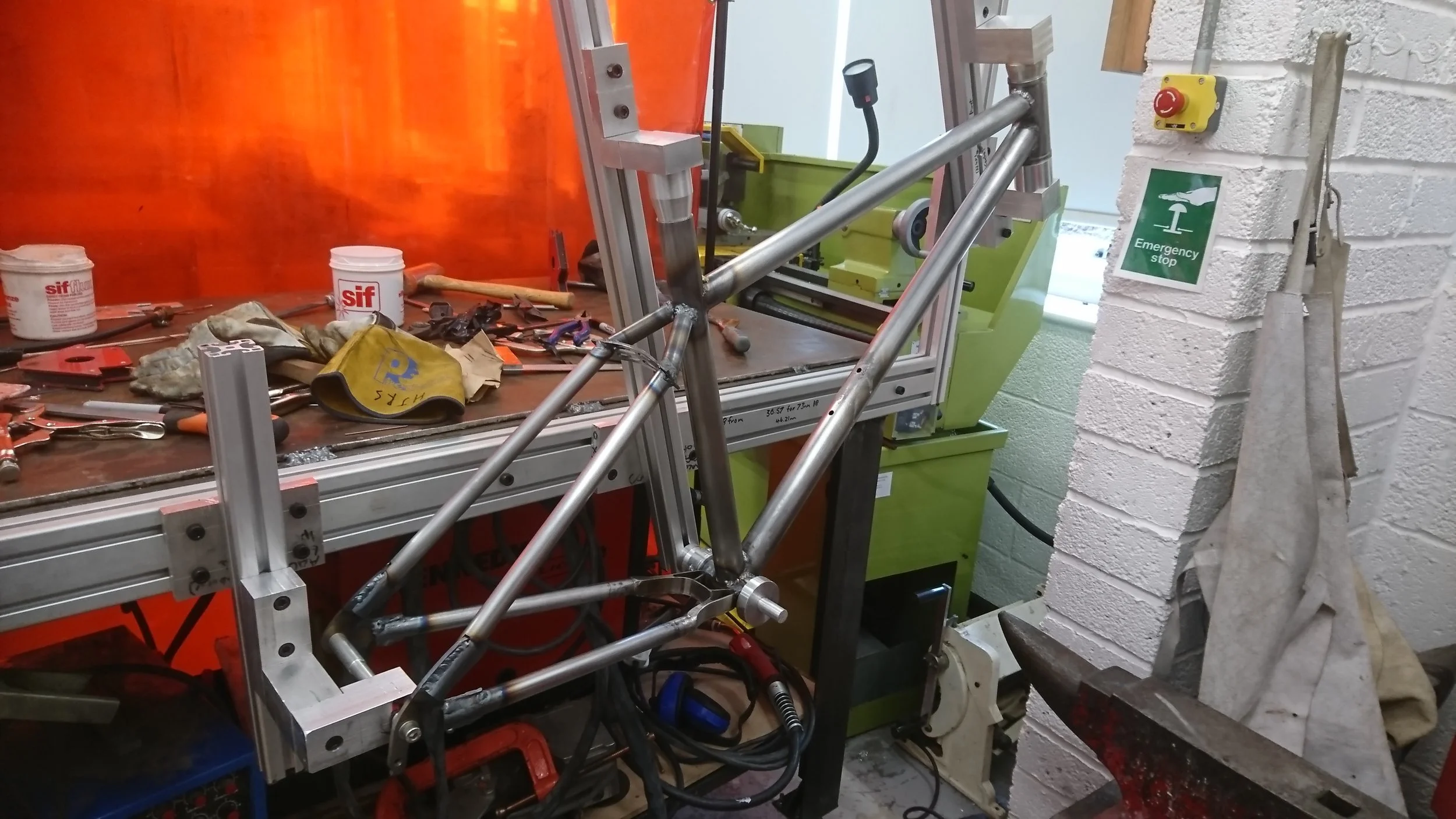
This project began with the production of a an adjustable fixture. The student had decided the dimensions and angles that he wanted to achieve in the final frame, so it was necessary to properly locate the head tube, bottom bracket and top of the seat tube. This was achieved using aluminium extrusion with different milled and/or turned locating blocks bolted to it.
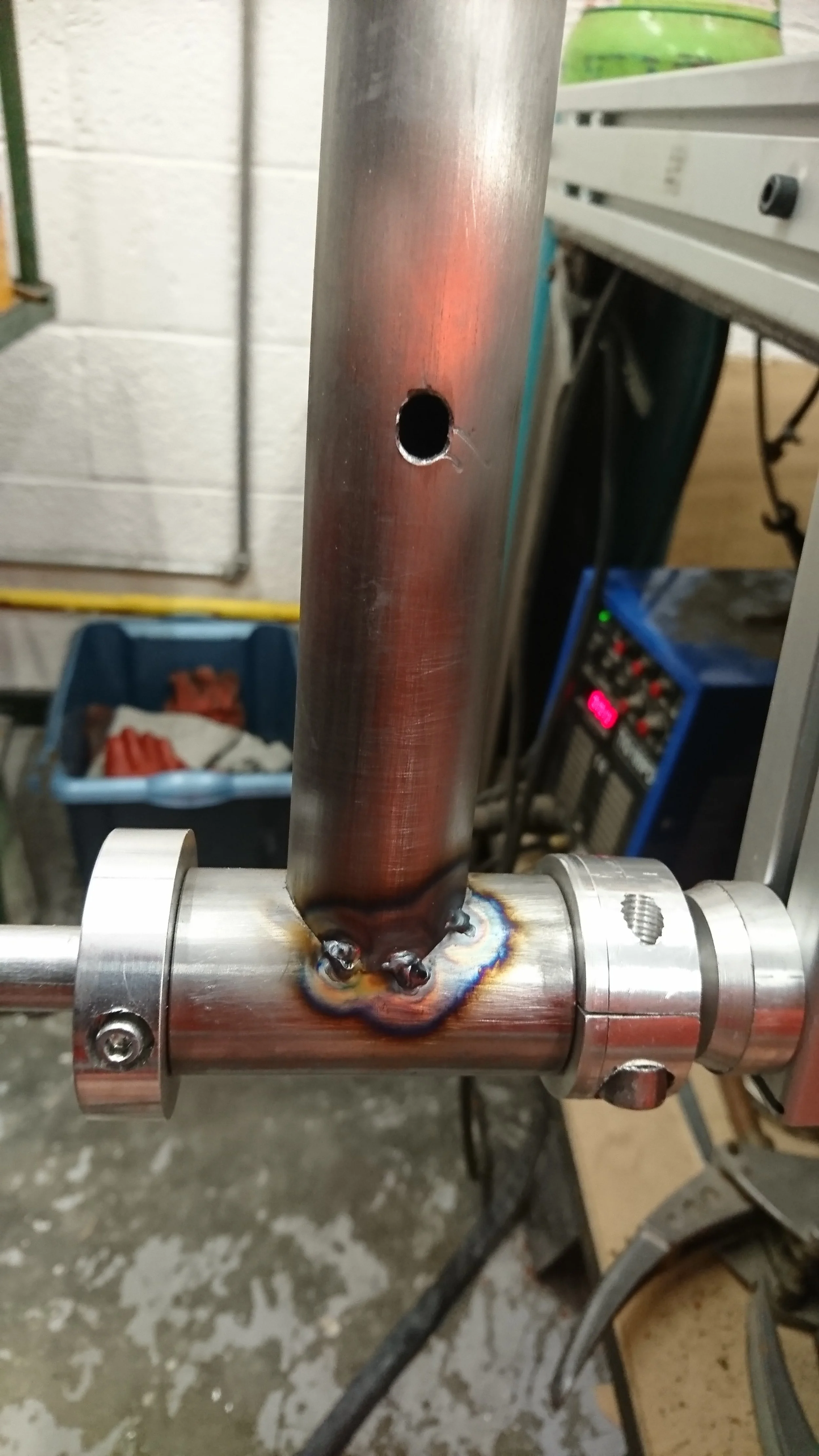
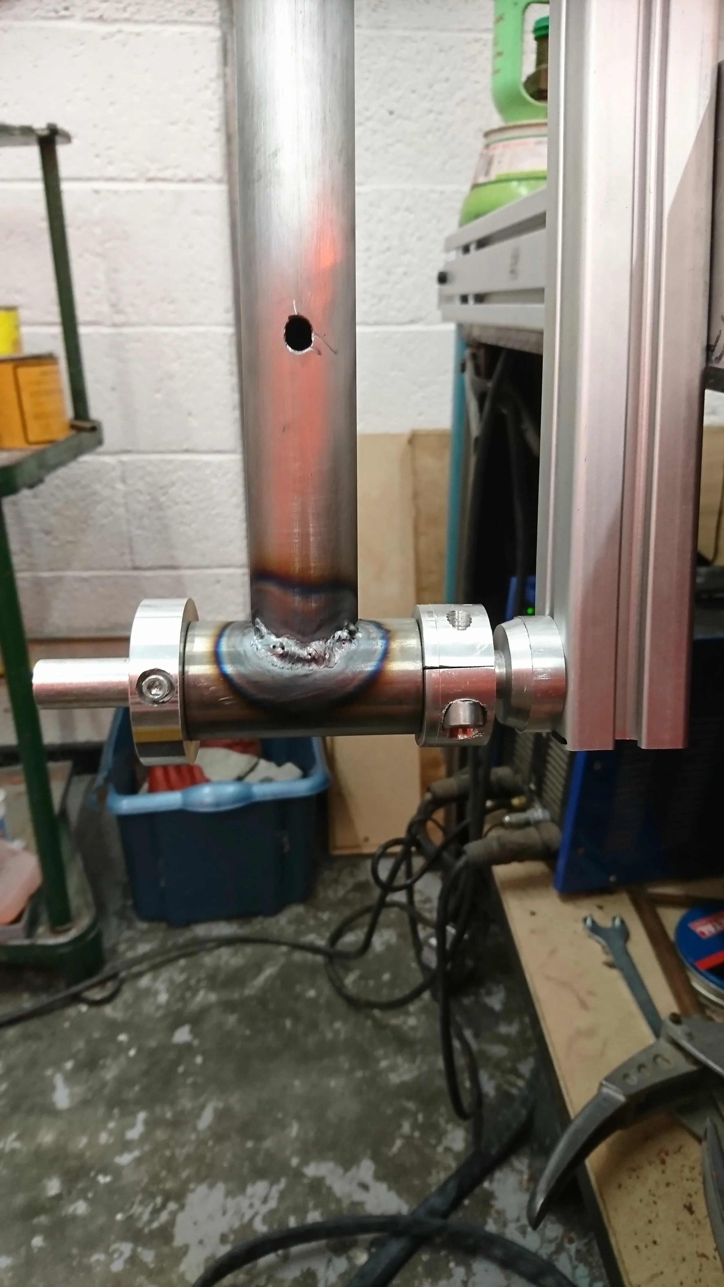
This is the bottom bracket, tacked to the seat post. Note the milled slot in the seat post to enable mounting of a drinks bottle etc.
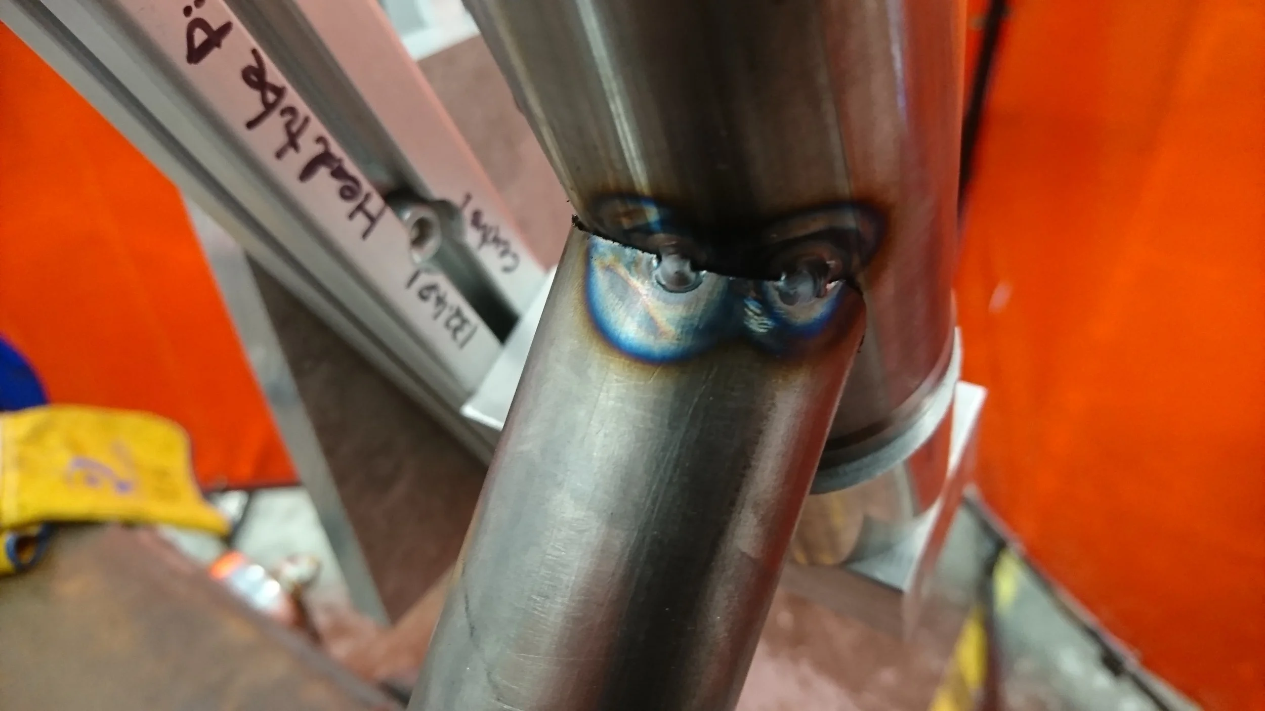
These tacks were completed by the student. This was his first attempt at welding on the actual frame. We had practised on several pieces of scrap steel before he felt sufficiently confident to attempt this. Not bad for a first go though!
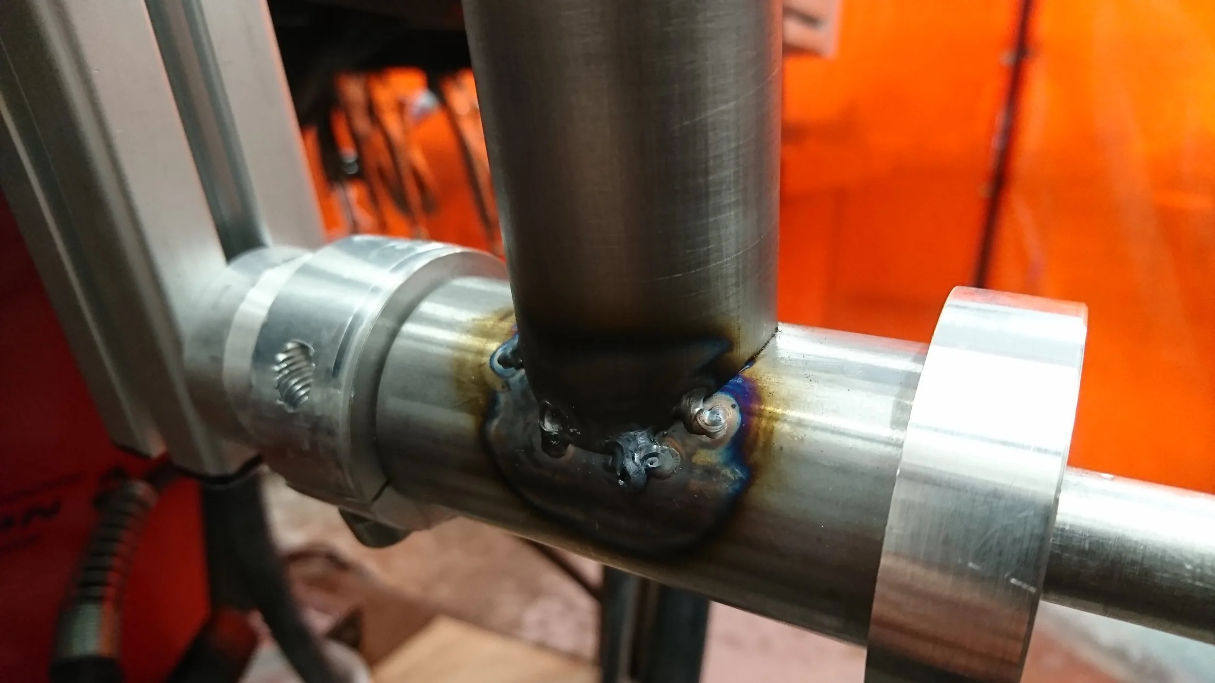
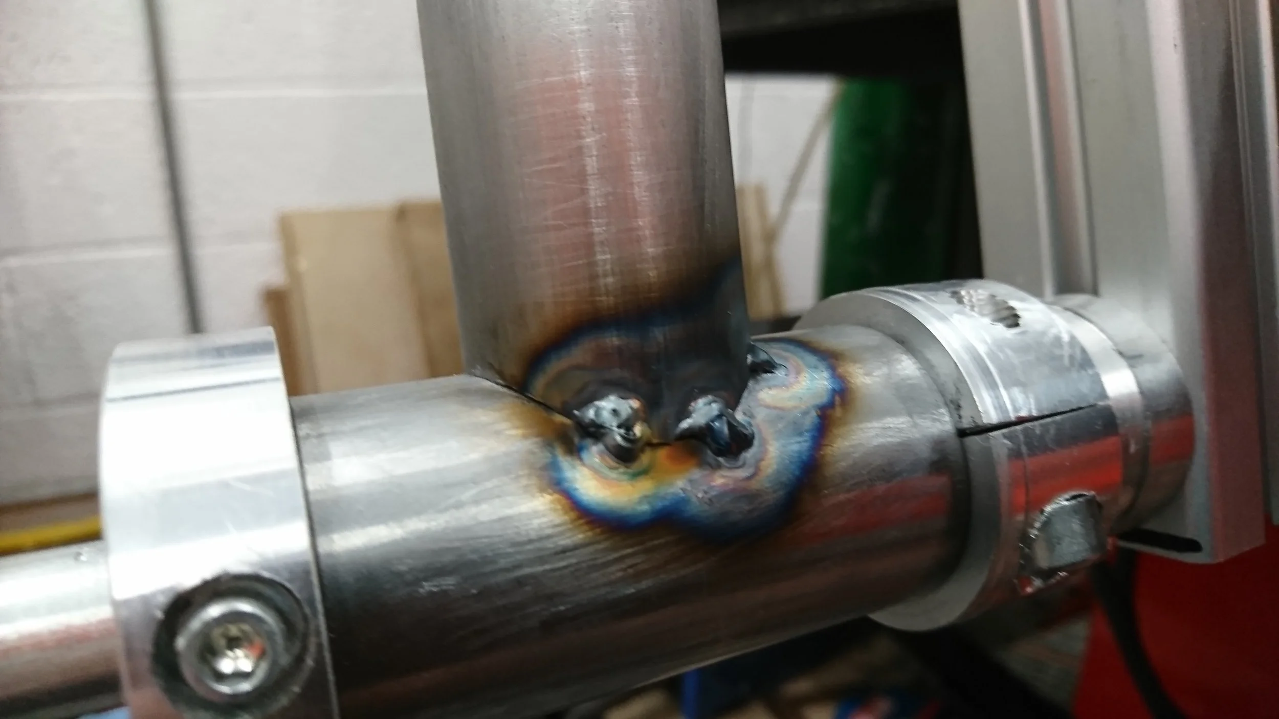
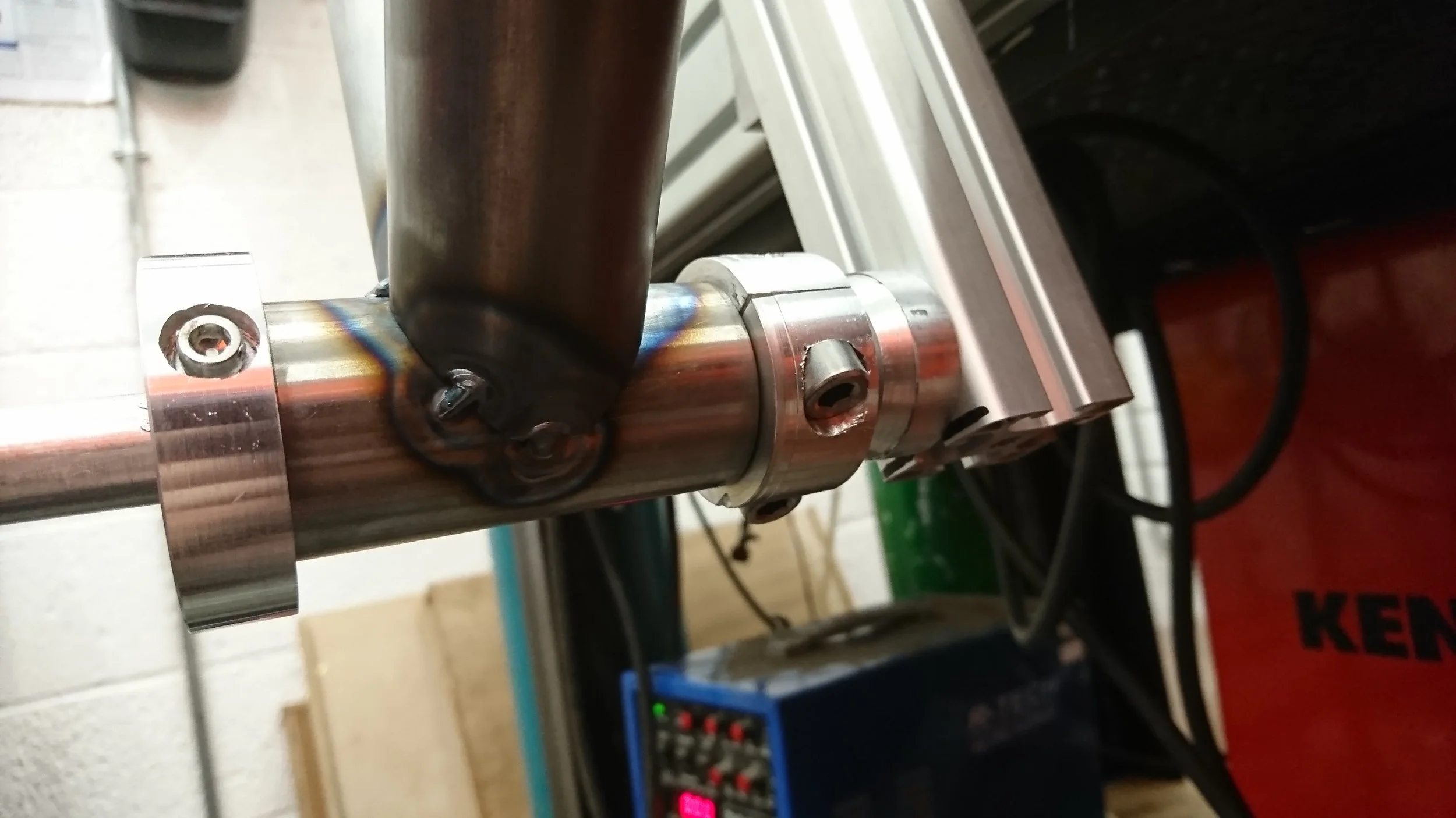
Tacks to the other side also. Note the locating collars with grub screws that ensure correct lateral position of the bottom bracket.
Now that the seat post is welded up fully where the down tube meets it, the downtube can be tacked on. The tubes were notched on a jig using a hole saw, before some tweaks to the profile with half-round and round files as required.
Now fully welded under where the downtube will be attaching.
Down tube tacked in underneath the bottom bracket.
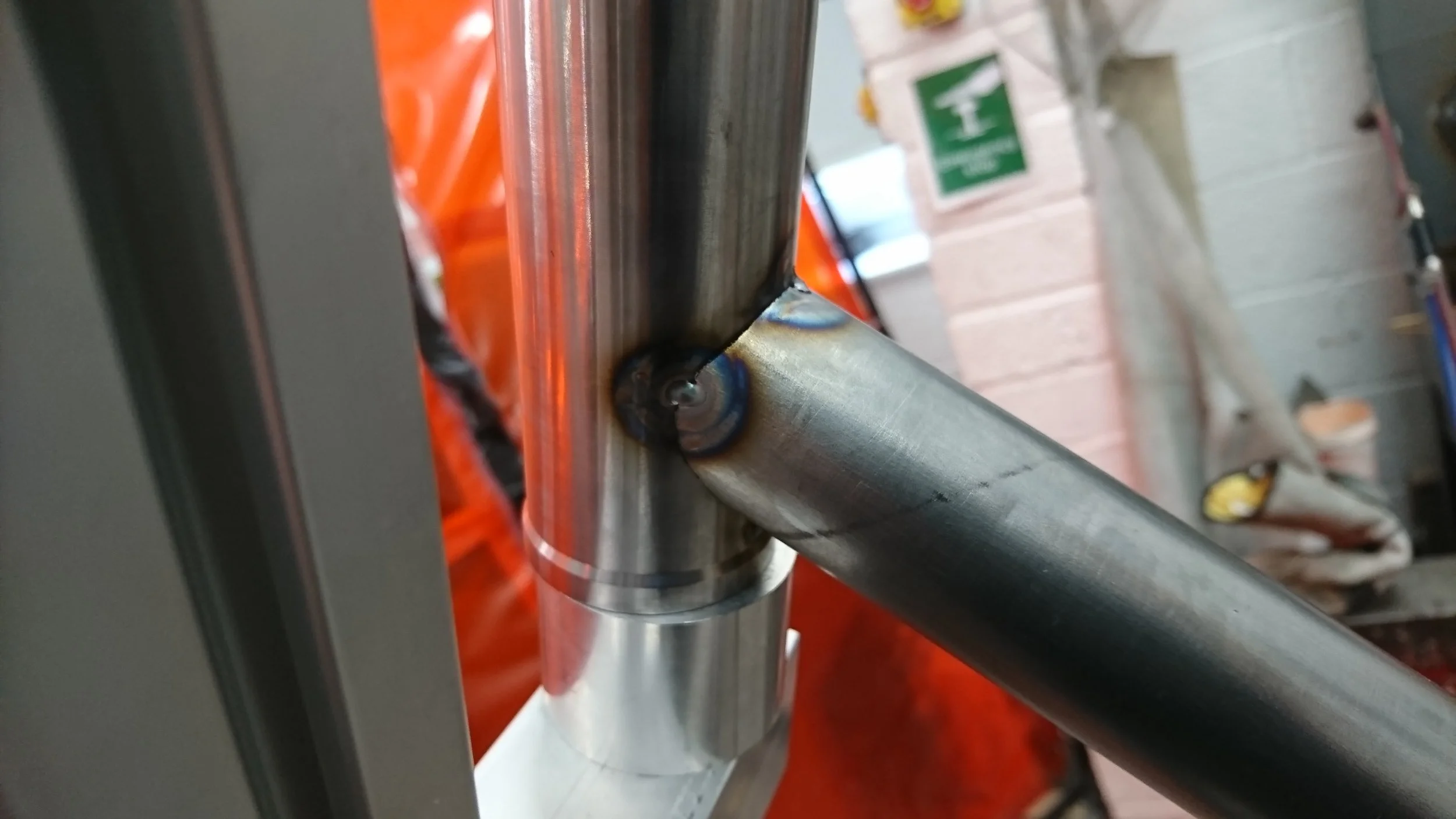
Tacking in the downtube at the head stock.
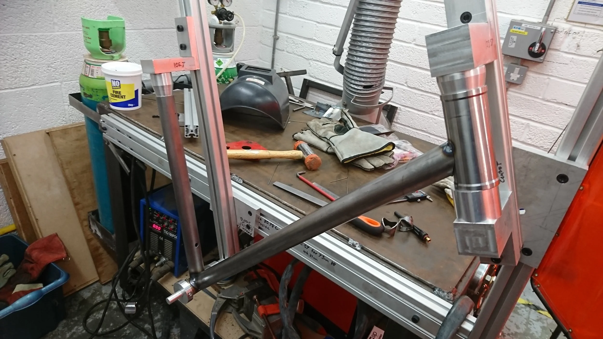
A wider shot gives a better view of the process.
Positioning was tricky for these tacks on the side nearest the fixture.
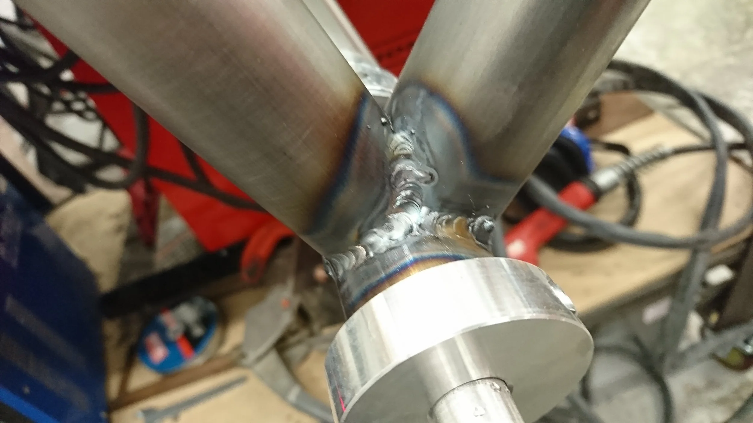
Fully welded seat post and down tube. This was a tight joint to get into with the TIG torch.
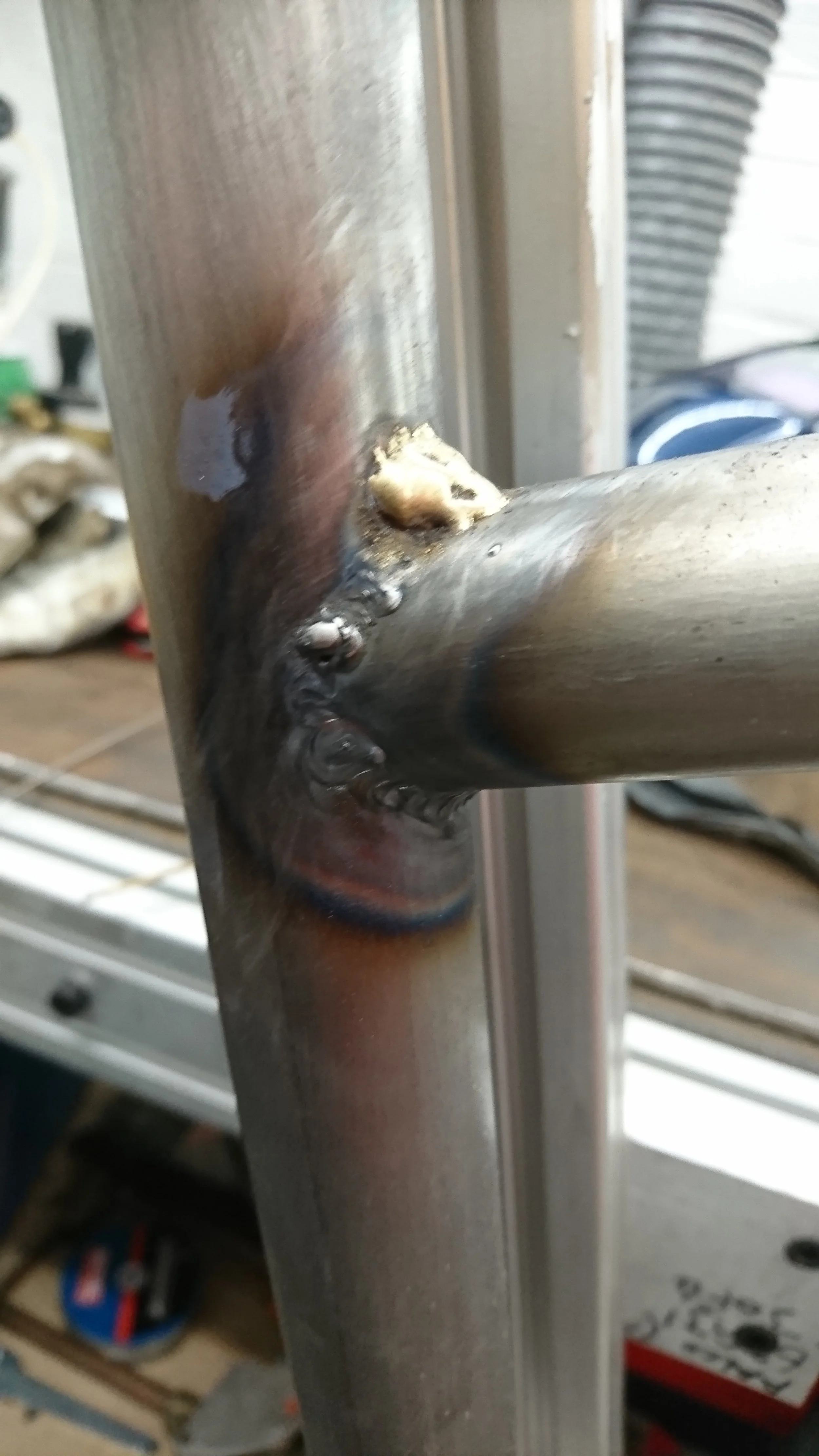
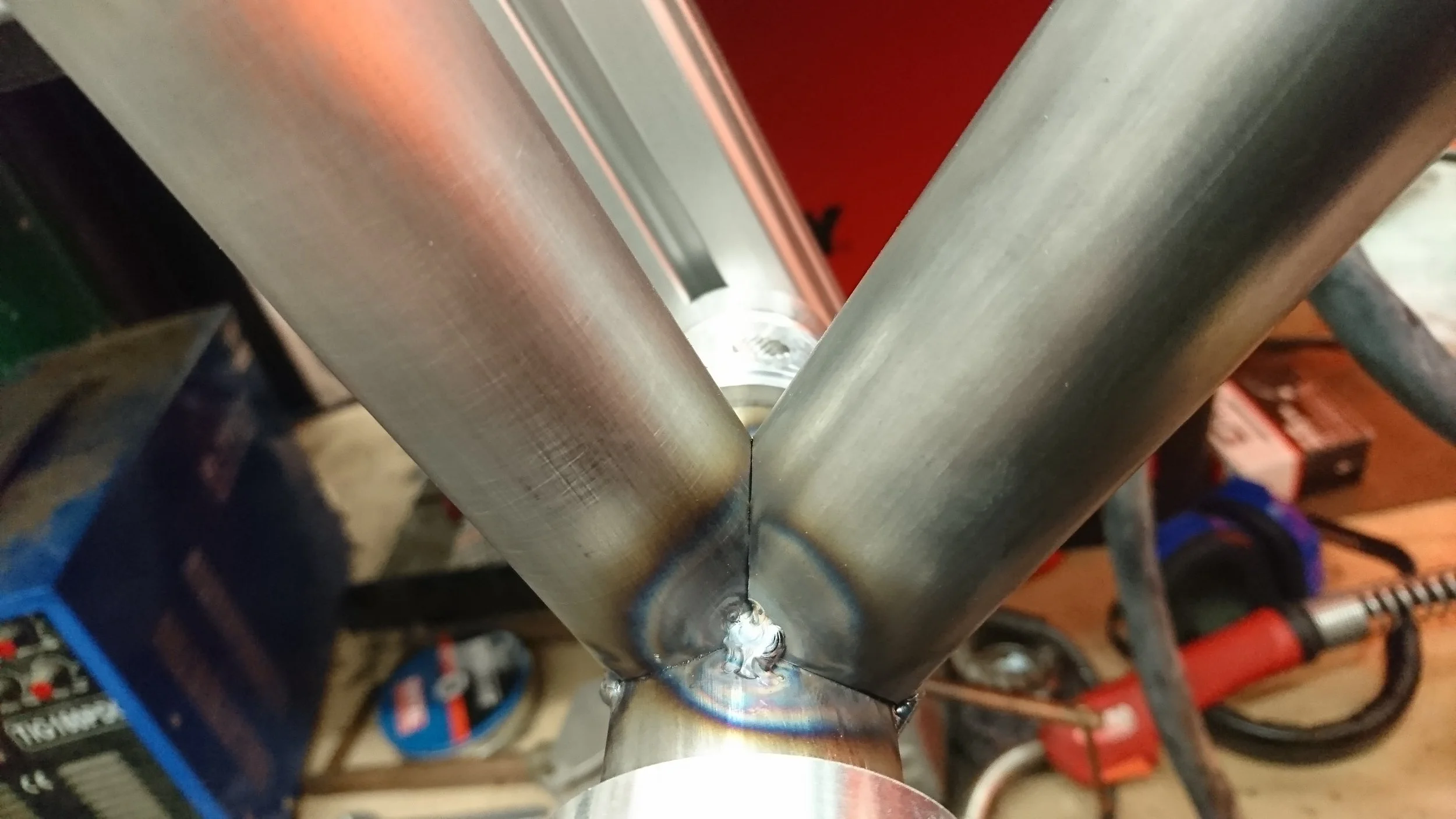
This is the top tube, attached to the seat post. The blob on the top of the joint is brass. We tried to do some TIG brazing to enable a smoothly blended brass fillet at each joint, however this didn't work particularly well for us and due to time constraints not facilitating a detailed testing regimen, the idea had to be abandoned.
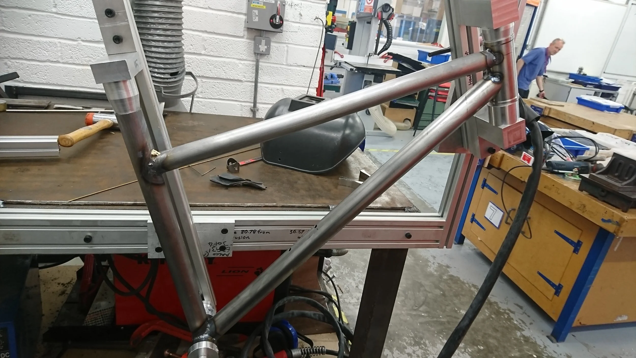
All of the front tubes tacked together.
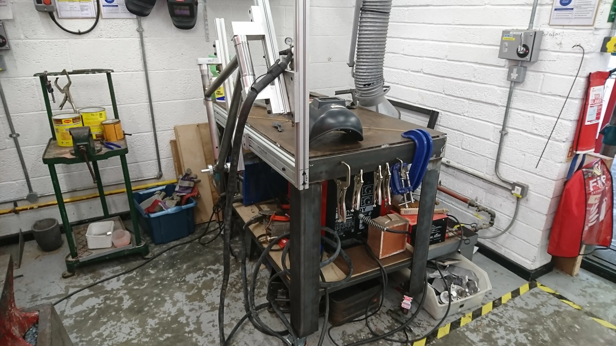
The welding bench looking tidy with all the welding clamps attached to one end.
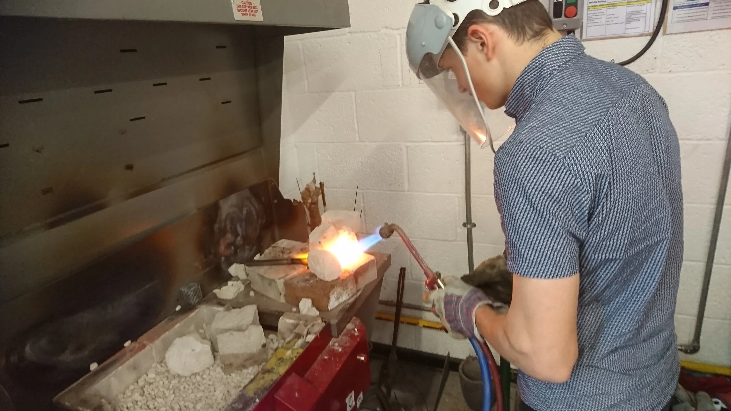
The student, heating up a component to be bent using the gas torch.
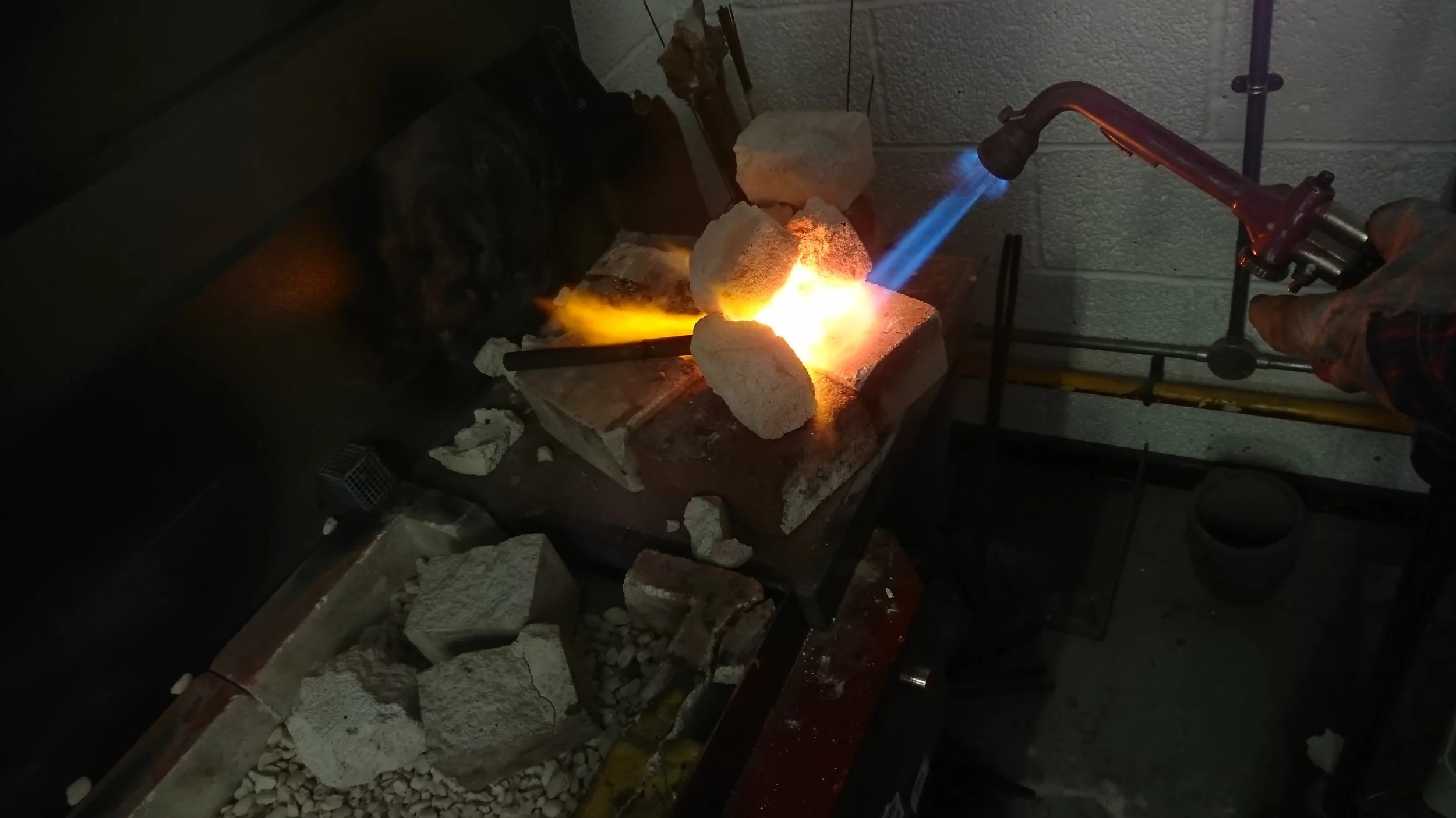
A small forge built from forge bricks helps concentrate the heat in a small space.
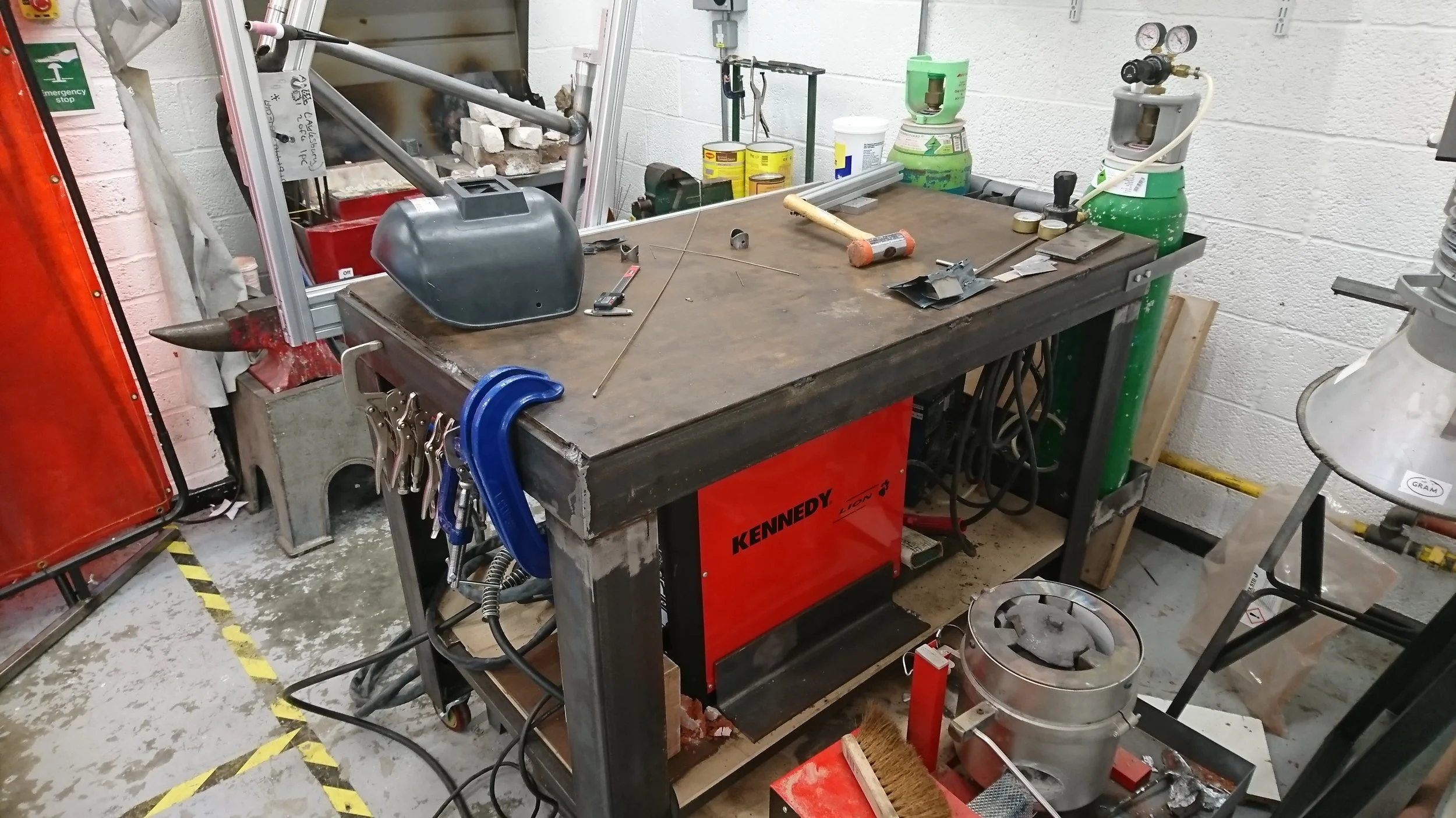
The shelf and bench height were designed to enable the welders to sit on the shelf, and still be able to roll the bench over the casting furnace for more compact storage when the casting furnace was not in use.

The fully assembled frame. Looks great and functional too! Take a look at the CNC Milling project to find out how we made the chainstay bracket that attaches them to the bottom bracket.